No products in the cart.
Mechanical Products, Hybrid Servo Drive, Stepper Motor Driver with Encoder
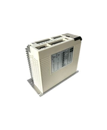
Hybrid Servo Drive SS1108
SKU: SS1108| ENCODER STEPPER MOTOR DRIVER TECHNICAL SPECIFICATIONS | |
| Voltage | 70VAC~130VAC |
| Current | 8.0 Amps |
$150,00
Hybrid Servo Drive SS1108
Hybrid Servo Drive Voltage: 70VAC~130VAC
Hybrid Servo Drive Current: 8.0AMPS
Hybrid Servo Drive: 2 Phase Servo Drive
Product Code: Hybrid Servo Drive SS1108
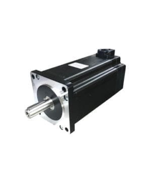
Motor Mounting
BLUE: A+
YELLOW: A-
BLACK: B+
RED: B-
2 Phase Encoder Stepper Motor Driver SS1108
The metal part of the panel where the drives are located must be EARTHED. Before giving Amperes to the drives, a voltage control must be done by entering a measuring device between NEUTRAL and EARTH cables. The ideal situation is zero volts.
In PLC, Arduino, Axis control card or specially designed cards, PULSE and DIR signals must be sent as 5V. For devices with signal outputs above 5 Volts, resistance must be entered into the PULSE and DIR signal output cables to be distributed individually in minus or plus driving. For example, the resistance required for 24Volt output is 1.8KΩ.
ALARM USE; ALARM connection of the drive is normally open dry contact. The use of ALARM required for CNC routers, ALM + outputs of hybrid servo drives on all axes for parallel connection are bridged between themselves and ALM – outputs are bridged between themselves. If the axis control card signal input is negative, the ALM – lead is connected to the power supply – output, the ALM + lead is connected to the E-Stop input. When any of the drives on the axes are alarmed, the signal will reach E-stop and mach3 will make emergency stop. It is ensured that the signal from the power supply is 5Volt or 24 Volt as acceptable by the axis control card.
Since the inputs are + in PLCs, ALM +s will all be connected to the PLC FEED 24 Volt +, ALM -s will be combined and connected to the input input selected for the alarm.
PEND USE: The PEND connection of the drive is a normally closed dry contact. By connecting in series, PEND + of the first driver is connected to the power supply, PEND – is connected to the PEND + input of the other driver. PEND – output of the last driver is connected to the input input. Since it is normally closed, there is a continuous signal. The signal is cut off when an alarm occurs.
Please click here for product video (1) : Hybrid Servo Drive
Please click here for product video (2) : Hybrid Servo Drive
Please click here for product video (3) : Hybrid Servo Drive
Hybrid Servo Drive SS1108 Product Video
The maximum power parameter settings allowed by the factory for SS1108 drives are as follows.
86BHH76-380p-40Mp => PR001->25, PR004->50
86BHH114-450p-40Mp => PR001->45, PR004->70
86BHH150-600-40Mp => PR001->40, PR004->70
ALARM CONDITIONS
| PROBLEMS | POSSIBLE CAUSES | SOLUTIONS |
| Motor Does Not Rotate | No electricity | Check the electrical input |
| Pulse signal does not reach the driver | Check signal input | |
| The signal is given as 24 Volts, a 1.8kΩ resistor will be connected to the PULSE and DIR inputs, or the pulse signal comes at too low voltage. It can be understood by measuring the voltage of the DIR signal. | ||
| Drive is DISABLED | ENABLE inputs are receiving a 5 volt signal, turn off the signal | |
| ALM Err_00 | High Voltage | Check the power supply output voltage (drive supply voltage) |
| ALM Err_01 | High Voltage | Check the power supply output voltage (drive supply voltage) |
| ALM Err_02 | High Amps | Check the motor cables and correct the short circuit. The drive trips as soon as it is switched on |
| ALM Err_03 | Incorrectly connected encoder cable | As soon as the movement starts, the display counter advances a little bit to alarm because there is no encoder signal. Check the encoder connection. Check that the sockets are fully seated. Check if there is a broken wire in the encoder cable. The motor encoder output cable may be broken by force or the encoder reader board behind the motor may be broken. The encoder disk may have slipped out of place or scorched due to high temperature. Replace the encoder cable, replace the encoder reader, replace the encoder disk, set parameter 14=>1 and turn the drive to open loop mode, i.e. turn off encoder tracking. |
| Motor cable incorrectly connected | Check the motor cable. The motor cable color sequence is important (blue, yellow, black, red). The drive trips as soon as it is switched on. The extension cable between the drive and the motor may be broken or split at the junction. | |
| Step missed it. | Turn the drive off and on. The motor shaft may be contracted. There may be mechanical jamming. Test by taking the engine out and running it at idle. Remove any mechanical binding. Replace with a larger motor. | |
| Motor or drive is defective | Replace motor or drive | |
| Don’t go to the wrong position | Microstep setting is incorrect | Set parameter 8 to the correct coefficient (factory value 1600 pulse=1 turn) |
| Control signal is receiving interference | Remove the parasite by grounding | |
| Stopping the engine in motion | Power supply output voltage is too low | Increase drive supply voltage |
| Departure time is too short | Extend departure time |


There are no reviews yet.