No products in the cart.
Electronic Products, Servo Motors, Incremental Servo Motors, Servo Motor Set
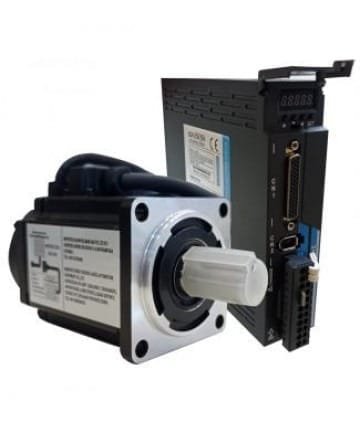
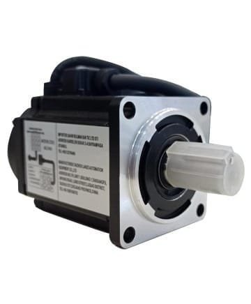
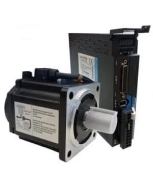
Multi Absolute Servo Motor 0.4 kW - 60LZ400 - LZ100
SKU: Multi Absolute - 60LZ400 - LZ100| POWER | 0.40 kW |
| TORQUE | 1.27 Nm |
| RPM | 4500 rpm/min |
| FLANGE | 60×60 mm |
$240,00
Servo Motor Drive Alarm List Servo Motor Drive Position Control Connection Diagram Servo Motor Mounting Dimensions
60LZ400 – LZ100 Multi Absolute Servo Motor Types
60LZ400 – LZ100 Multi Absolute servo motor types vary according to their features. The 60LZ400 – LZ100 Multi Absolute servo motor has a power rating of 0.4W and is also an ideal multi absolute servo motor for use in small medical devices, industrial automation equipment, robotic devices and other precision applications. In this way, the controlled load of the application can be kept at a constant position or speed. Preferred by many manufacturers, the 60LZ400 – LZ100 Multi Absolute servo motor range offers rational solutions. With a holding torque of 1.27 Nm, it ensures that your servo motor remains professionally stable. In addition, the flange value of 60x 60 mm supports the efficient and safe operation of your machine. By ordering the 60LZ400 – LZ100 Single Absolute servo motor type from Sahin Rulman immediately, you can ensure that your machine works professionally.
60LZ400 – LZ100 Multi Absolute Servo Motor Prices
Multi Absolute servo motor prices generally vary according to the feature. The price of 60LZ400 – LZ100 Multi Absolute servo motor drive with 220 volt power is $240.00. You can order the 60LZ400 – LZ100 Multi Absolute servo motor type, which increases its performance and functionality while using your machine.
60LZ400 New Generation Servo Motor Technical Video
60LZ400 New Generation Servo Motor Jog Settings
60LZ400 New Generation Servo Motor Operation Example
60LZ400 Kw Servo Motor Specifications
- Servo motor working environment: Operation: 0℃~40℃ Storage: -40℃~50℃
- Poles: 4-pole servo motor
- Absolute Single Circle: 17Bit
- Humidity maximum: 90%
- Insulation Class: B
- Servo Motor Protection Class: IP54
- Servo Motor Isolation Voltage: AC1500V, 1 minute
- Servo Motor Insulation Resistance: DC500V, 10MΩ or more
- Structure: Self-cooled servo motor
- Vibration: 2.5G or less
- Altitude: 1000m or less
- Operation: The servo motor runs continuously.
- Servo Motor Assembly: Flange Mounting
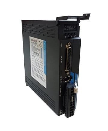
New Generation Absolute 60LZ400 Servo Motor Technical Specifications
| Model | P100S-40 | P100S-75 |
| Power | 0.05kW~0.4kW | 0.75kW~1kW |
| Main Circuit | 1 Phase AC220V-15%~10%~50%/60Hz | |
| Control Mode | 0:Location. 1:Speed. 2: Torque. 3:Position and speed. 4:Position and torque. 5:Speed and torque | |
| Protection Function | Over speed, Over voltage, Under voltage, Over load, Abnormal main power, Abnormal encoder, Out of position error etc. | |
| Monitoring Function | Speed, Current position, Command pulse accumulation, Position deviation, Motor torque, Motor current, Operating status, etc. | |
| Control Input | 1:Servo on 2:Alarm clearing 3:CCWdrive inhibition 4:CCWdriveinhibition 5:Step counter clearing 6:Command pulse inhibition7:CCW torque limit 8:CW torque limit | |
| Control Output | Servo ready/Servo alarm/Positioning completion/Mechanical braking | |
| Regeneration Braking | Built-in/ Built-out | |
| Load | Less than 3 times the engine torque | |
| View | 5 LED digital display and 4 keys | |
| Contact | RS485 | |
Position Control Mod | Introduction Mod | 0:impulse+direction |
| 1:CCW/CW pulse | ||
| 2:A/B phase orthogonal pulse | ||
| 3:Internal position control | ||
| Electronic Gear Ratio | 1-32767/1-32767 | |
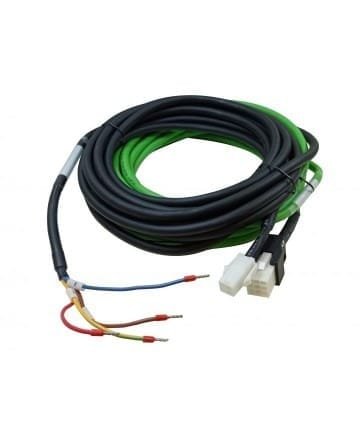
Signal Cable Pins and Colors;
| Pin No | Color | Function |
| 33 | Blue | BlackALM+ |
| 22 | Green Black | D- |
| 21 | Yellow Black | P- |
| 34 | Black | 0V |
| 34 | Blue | ALM- |
| 6 | Green | D+ |
| 5 | Yellow | P+ |
| 16 | Red | 24V |
80LZ1000 Series Internal Servo-ON Parameter:
PA53 => 1Motor selection with Servo Motor Drive Parameter Settings
| Alarm | |
| D02+ | Pin33 |
| D02- | Pin34 |
| If Alarm Input is Positive | |
| Pin33 | (+)24V |
| Pin34 | ALM İnput |
| If Alarm Input is Negative | |
| Pin33 | ALM İnput |
| Pin34 | 0 Volt |
Servo Motor Alarm List
| No | Error Name | Definition | No | Error Name | Definition |
| — | Normal | 29 | Alarm for torque overload | Motor load exceeds user-set values and range | |
| 1 | Excessive Speed | Motor speed is above the set values. | 38 | Encoder EEPROM communication read or write error | Encoder cable not connected Or encoder interface circuit fault |
| 2 | Main circuit overvoltage | Main circuit voltage too high | 39 | Data CRC check error | The motor encoder wrote no data and all 0. |
| 3 | Main circuit low voltage | Main circuit voltage too low | 40 | Model not supported | The drive does not support this motor model |
| 4 | Position overshoot | The value of the position deviation counter is above the set value. | 41 | You need to change the engine model | Current motor inconsistent with selected drive model |
| 5 | Overheating of the drive | High temperature of the driver | 42 | AC input low voltage | AC input low voltage |
| 6 | Speed booster saturation error | Speed adjustment for long-lasting saturation | 47 | Overvoltage in main circuit | Over-voltage when opening the main circuit |
| 7 | Driver blocking error | Speed adjustment at saturation for a long time | 50 | Encoder communication error | Driver and encoder not connected |
| 8 | Position deviation accumulation was out of range | The absolute value of the position deviation accumulation is above 2 30 | 51 | Encoder communication abnormal | After the encoder establishes communication, interruption and disconnection appear. |
| 11 | IPM module error | IPM smart module error | 52 | Encoder battery voltage insufficient alarm | Encoder battery voltage insufficient alarm, but the information is not lost and needs to be replaced as soon as possible |
| 13 | Drive overload | Servo drive and motor overload (instantaneous overheating) | 53 | Encoder battery voltage error alarm | Encoder battery voltage error alarm and storage information, an error occurred requiring the encoder to be reset. |
| 14 | Brake problem | Brake circuit Fault | 54 | Encoder error alarm | The encoder alarm without battery, but you need to reset the encoder again. |
| 18 | Relay switch fault | The actual state of the relay is different from the control state. | 55 | CRC check fails 3 times in a row | Encoder communication received data CRC verification 3 consecutive errors. |
| 19 | Error occurred when there was a delay to open the brake | Impact inputs before opening | 56 | MODBUS frame too long | MODBUS frame data received is too long |
| 20 | EEPROM error | EEPROM error | 57 | Abnormal MODBUS communication format | Incorrect setting of communication parameters or incorrect address or value |
| 21 | FPGA module error | FPGA module error | 58 | Single turn position error | Single rotation position offset stored by the drive exceeds encoder resolution |
| 23 | Current collection circuit malfunction | Akım toplama devresi arızası | 59 | Encoder reports CF error | The encoder constantly reports CF domain error and you need to reset the encoder |
Servo Motor Drive Position Control Wiring Diagram

Servo Motor Mounting Dimensions


There are no reviews yet.