No products in the cart.

Electronic Products, Servo Motor Set, Servo Motors
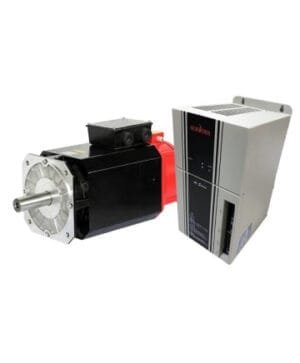
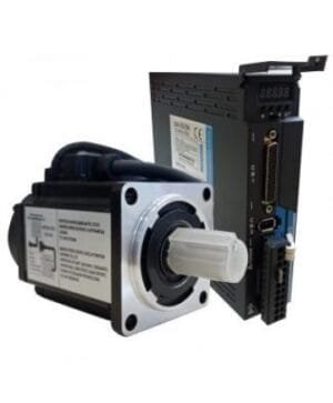
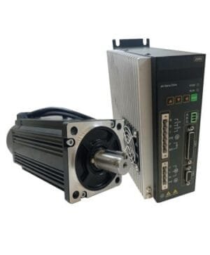
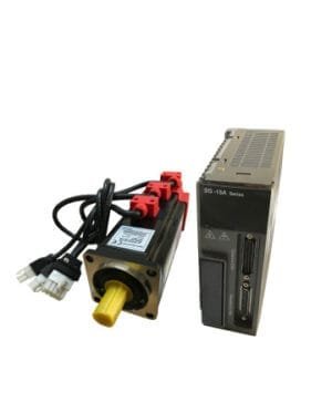
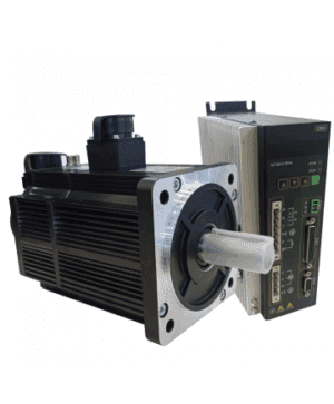
Servo Motor 3 kW | 130LZ-M20015 | LZ3a-50LM
SKU: 130LZ - M20015 - LZ3a-50LM| SERVO MOTOR TECHNICAL SPECIFICATIONS | |
| POWER | 3.0 kW |
| TORQUE | 20 Nm |
| RPM | 1500 rpm/min |
| FLANGE | 130×130 mm |
$950,00
Servo Motor Drive Alarm List
Servo Motor Drive Position Control Wiring Diagram
Servo Motor Mounting Dimensions
The model 130LZ-M20015 LZ3a-50LM servo motor with 3.00 kW and 220 volt voltage current has a torque value of 20 Nm and reaches 1500 revolutions per minute. You can buy 3.00 kW servo motor with 130×130 flange size by reviewing the price.
130LZ-M20015 New Generation Servo Motor Technical Video
130LZ-M20015 New Generation Servo Motor Jog Settings
130LZ-M20015 New Generation Servo Motor Operation Example
3 Kw Servo Motor Features
- Servo motor working environment: Operation: 0℃~40℃ Storage: -40℃~50℃
- Poles: 4-pole servo motor
- Absolute Single Circle: 17Bit
- Humidity maximum: 90%
- Insulation Class: B
- Servo Motor Protection Class: IP54
- Servo Motor Isolation Voltage: AC1500V, 1 minute
- Servo Motor Insulation Resistance: DC500V, 10MΩ or more
- Structure: Self-cooled servo motor
- Vibration: 2.5G or less
- Altitude: 1000m or less
- Operation: The servo motor runs continuously.
- Servo Motor Assembly: Flange Mounting
New Generation Absolute 80LZ1000 LZ-100A Servo Motor Technical Specifications
| Model | P100S-40 | P100S-75 |
| Power | 0.05kW~0.4kW | 0.75kW~1kW |
| Main Circuit | 1 Phase AC220V-15%~10%~50%/60Hz | |
| Control Mode | 0:Location. 1:Speed. 2: Torque. 3:Position and speed. 4:Position and torque. 5:Speed and torque | |
| Protection Function | Over speed, Over voltage, Under voltage, Over load, Abnormal main power, Abnormal encoder, Out of position error etc. | |
| Monitoring Function | Speed, Current position, Command pulse accumulation, Position deviation, Motor torque, Motor current, Operating status, etc. | |
| Control Input | 1:Servo on 2:Alarm clearing 3:CCWdrive inhibition 4:CCWdriveinhibition 5:Step counter clearing 6:Command pulse inhibition7:CCW torque limit 8:CW torque limit | |
| Control Output | Servo ready/Servo alarm/Positioning completion/Mechanical braking | |
| Regeneration Braking | Built-in/ Built-out | |
| Load | Less than 3 times the engine torque | |
| View | 5 LED digital display and 4 keys | |
| Contact | RS485 | |
Position Control mode | Entrance mode | 0:impulse+direction |
| 1:CCW/CW pulse | ||
| 2:A/B phase orthogonal pulse | ||
| 3:Internal position control | ||
| Electronic Gear Ratio | 1-32767/1-32767 | |
Signal Cable Pins and Colors;
| Pin No | Color | Function |
| 33 | Blue | BlackALM+ |
| 22 | Green Black | D- |
| 21 | Yellow Black | P- |
| 34 | Black | 0V |
| 34 | Blue | ALM- |
| 6 | Green | D+ |
| 5 | Yellow | P+ |
| 16 | Red | 24V |
80LZ1000 LZ3a-50LM Series Internal Servo-ON Parameter:
PA53 => 1
Motor selection with Servo Motor Drive Parameter Settings
| Alarm | |
| D02+ | Pin33 |
| D02- | Pin34 |
| If Alarm Input is Positive | |
| Pin33 | (+)24V |
| Pin34 | ALM İnput |
| If Alarm Input is Negative | |
| Pin33 | ALM İnput |
| Pin34 | 0 Volt |
Servo Motor Alarm List
| No | Error Name | Definition | No | Error Name | Definition |
| — | Normal | 29 | Alarm for torque overload | Motor load exceeds user-set values and range | |
| 1 | Excessive Speed | Motor speed is above the set values. | 38 | Encoder EEPROM communication read or write error | Encoder cable not connected Or encoder interface circuit fault |
| 2 | Main circuit overvoltage | Main circuit voltage too high | 39 | Data CRC check error | The motor encoder wrote no data and all 0. |
| 3 | Main circuit low voltage | Main circuit voltage too low | 40 | Model not supported | The drive does not support this motor model |
| 4 | Position overshoot | The value of the position deviation counter is above the set value. | 41 | You need to change the engine model | Current motor inconsistent with selected drive model |
| 5 | Overheating of the drive | High temperature of the driver | 42 | AC input low voltage | AC input low voltage |
| 6 | Speed booster saturation error | Speed adjustment for long-lasting saturation | 47 | Overvoltage in main circuit | Over-voltage when opening the main circuit |
| 7 | Driver blocking error | Speed adjustment at saturation for a long time | 50 | Encoder communication error | Driver and encoder not connected |
| 8 | Position deviation accumulation was out of range | The absolute value of the position deviation accumulation is above 2 30 | 51 | Encoder communication abnormal | After the encoder establishes communication, interruption and disconnection appear. |
| 11 | IPM module error | IPM smart module error | 52 | Encoder battery voltage insufficient alarm | Encoder battery voltage insufficient alarm, but the information is not lost and needs to be replaced as soon as possible |
| 13 | Drive overload | Servo drive and motor overload (instantaneous overheating) | 53 | Encoder battery voltage error alarm | Encoder battery voltage error alarm and storage information, an error occurred requiring the encoder to be reset. |
| 14 | Brake problem | Brake circuit Fault | 54 | Encoder error alarm | The encoder alarm without battery, but you need to reset the encoder again. |
| 18 | Relay switch fault | The actual state of the relay is different from the control state. | 55 | CRC check fails 3 times in a row | Encoder communication received data CRC verification 3 consecutive errors. |
| 19 | Error occurred when there was a delay to open the brake | Impact inputs before opening | 56 | MODBUS frame too long | MODBUS frame data received is too long |
| 20 | EEPROM error | EEPROM error | 57 | Abnormal MODBUS communication format | Incorrect setting of communication parameters or incorrect address or value |
| 21 | FPGA module error | FPGA module error | 58 | Single turn position error | Single rotation position offset stored by the drive exceeds encoder resolution |
| 23 | Current collection circuit malfunction | Current collection circuit malfunction | 59 | Encoder reports CF error | The encoder constantly reports CF domain error and you need to reset the encoder |
Servo Motor Drive Position Control Wiring Diagram

Servo Motor Mounting Dimensions

Technical Drawing

There are no reviews yet.